The aluminum extrusion process transforms aluminum alloy into cross-sectional products. This process has an incredibly wide variety of different applications. Aluminum is especially well-suited for extrusion, as it is uniquely malleable and stable.
Aluminum Extrusion Design
When beginning the process of aluminum extrusion design, there are many factors to be considered. One of the first and most important variables is circle size — it is vital to find a manufacturer that handles the desired circle size, as not every manufacturer offers a full range of options. Additionally, weight-per-foot must be taken into account before beginning the design process. These measurements can impact the operation of the press and determine the necessary press size.
To achieve the best product, designers must also account for shape constraints. For the extrusion process to work optimally, it is best to avoid high tongue ratios.
Best Practices
There are a number of design practices that can help to ensure a better final product. These include:
- Utilization of webs, grooves, and ribs
- Generous tapers
- Balanced walls
- Avoiding or limiting hollows
- Minimizing the perimeter/cross-section ratio
- Practicing symmetry and limiting asymmetrical details
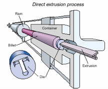
There are two extrusion processes, direct and indirect. With direct, the ingot moves relative to the container wall; with indirect, the die moves. Under pressure, the ingot or billet, confined in a container, is forced through a die opening to form an elongated shape or tube. To produce a tube or hollow shapes, a mandrel establishes the inside contour. Mandrels can either be separate tools or an integral part of specialized dies.
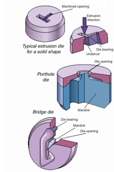
There are three types of extrusion dies — porthole and bridge designs for hollow shapes and machined blanks for solid shapes. Dies are usually machined from A13 steel at 47 to 51 Rockwell B.

Certain aluminum alloys lend themselves well to the extrusion process. Extrusion is an economical way for designers to create parts with individually engineered shapes. This versatility lets designers place metal only where it is structurally needed or hollow out parts for greater utility and economy.
With aluminum extrusions, there is no need to limit design shapes to “standard” profiles as is often a requirement with steel and other materials. The ability to tailor shapes for each application also helps consolidate parts and eliminate secondary joining processes common with designs made from sheet stock.
It is paramount for most designers to have a clear knowledge of 6000 (Al-Mg-Si) Series alloys, mostly 6061 and 6063. Alloy 6061 is often referred to as the “plain carbon steel of aluminum” — the workhorse standard for structural parts. And though other alloys fit the bill for special needs, 6061 is one of the most cost effective. It is considerably stronger than common aluminum-sheet alloys such as 5052 H32. It has a 35,000 psi yield strength compared to 23,000 psi for 5052 H32.
One of the biggest mistakes designers make in alloy specification, however, stems from concerns over strength. High-strength alloys referenced in the Aluminum Standards may at first glance appear to be appropriate for a new design. But there may be hidden drawbacks associated with these specialized alloys which preclude common use, high cost being only one.
For instance, 7075-T6 aluminum has a minimum yield strength of 70,000 psi. But, the alloy can’t produce intricate shapes, isn’t weldable, and is prone to corrosion. For an aircraft wing spar, it may well be an excellent choice, but for a truck frame it will likely cost too much and not perform well.
It is also important to note that higher material strength doesn’t necessarily boost part rigidity. A stronger aluminum alloy will help only if peak or cyclic loading conditions make it imperative to use a higher strength material.
If the long cycle fatigue or short cycle peak loads in a part do not exceed the capability of the lower strength alloy, then a higher strength alloy does not add to rigidity. In general, a 50% increase in thickness will make an aluminum part as stiff as steel but at half its weight.
Extruded Aluminum Alloy Selection
Tri-State Aluminum’s most commonly used alloys for extrusions are:
1xxx series — Containing 99% aluminum, 1xxx series aluminum is often used in applications requiring high weldability due to their track record of high corrosion resistance and excellent workability.
6005/6005A —When comparing 6005 aluminum and 6005A, they differ in chemical composition but are similar in some applications. For instance, 6005 aluminum has a high silicon amount, reducing its melting point but improving its extrudability. 6005A aluminum also has more chromium to reduce the risk of stress corrosion and increase its toughness. It also has extra manganese to improve its extrudability and strength.
6063 — A good match for decorative purposes with a good surface finish or for features difficult to extrude such as thin walls or fine details. It extrudes fairly easily and is available in multiple tempers. The alloy also has 25,000 psi minimum yield and 30,000 psi minimum ultimate strength when T6 tempered. It resists corrosion but has a low weld strength though it welds readily.
6061 — Stronger than 6063, this alloy is a structural staple in the transportation and machined parts industries. It has a proven track record and an extensive database of properties which include minimum ultimate yield and tensile strengths of 35,000 and 38,000 psi, respectively. The alloy extrudes and welds readily. These attributes coupled with high fracture toughness and good fatigue strength have made it a shoe-in for welded structural members which include auto, truck and trailer frames, railroad cars, and pipelines.
Factoring in Cost in Aluminum Extrusion Design
In comparing aluminum product forms & alloys, an extrusion is said to cost about the same as coiled sheet — at 48 in. or so wide. Getting the sheet slit to a narrow width, cut off, and formed sequentially adds cost to the part. At the end of the sequence, the part has the properties found in an extrusion. The difference is that the extrusion has all those properties in the based priced lineal without the add-ons. The extruded parts are also typically stronger and lighter than their formed-sheet counterparts.
Compared to castings, the greatest cost saver is in tooling. It is not un-usual for semipermanent mold tooling that produces small parts to cost upwards of $30,000. Larger part tooling can tip the scale at over $100,000. For extrusions, many small custom dies go for under $1,000 and seldom surpass $5,000 even for large and complex hollows.
The casting industry also typically charges customers for replacement tools when the originals wear out. Extrusion suppliers, by convention, normally pay for replacement dies.
Furthermore, it is not uncommon to spend $1,000 or more to machine prototype parts from solid stock. With extrusions, designers spend virtually about the same amount on first article dies which also serve production when proven. Another factor is the time, often months, that it takes to make and prove casting tools. Extrusion dies, on the other hand, often take only a few weeks to build and prove.
Design Trouble Spots for Aluminum Extrusions
The more unsymmetrical or unbalanced a shape, the less likely it is to remain straight or hold curves and general dimensions. Major wall-thickness variations also cause problems. Generally, the minimum wall thickness should be at least half that of the thickest within a profile. Distortion can be a problem otherwise. Walls with different thicknesses also cool at different rates during heat-treat quenching, and add distortion as well.
Inexperienced designers frequently specify walls that are too thin. The minimum wall thickness goes up as the extrusion shape gets larger. In most alloys, for example, a 0.062-in. wall is possible in a 3-in.-wide shape but not possible for one 10-in. wide.
Narrow shapes with deep gaps can cause problems. An example is an opening that is 0.25-in. wide but more than an inch deep. Here the die steel forming the opening is hard to support and prone to break. Ratios of depth-to-opening should be kept under 4:1.
Similarly, some shapes that are not actually hollow must be produced on a hollow-type die. Otherwise the area of the die tongue can’t withstand the extrusion pressure force and will break.
Aluminum Extrusion Terminology
The extrusion industry has its own set of special terms pertaining to press and die work.
Circle size: The smallest circle that completely encloses a part’s profile. This is an important indicator of producibility. It helps determine the size of the press needed to produce the shape. Some shapes will be as small as 1-in. circle size. Up to 12-in. circle sizes are common. Circle sizes from 19 to 30 in. exist, but are highly specialized and the shapes tend to be quite expensive.
Press tonnage: Extrusion presses are referred to by tonnage — the amount of force available on the ram to press the billet through the die. Under 1,000 tons is considered quite small, while 1,100 to 5,000 tons is common. Presses up to 12,000 tons are highly specialized.
Factor: An indicator of how difficult the profile will be to extrude. Factor is the ratio of the circle size to the surface perimeter. For example, a round solid rod would have a low factor of perhaps eight. A round shape with many splines around the periphery might have a factor of 50.
Extrusion ratio: Similar to Factor in that it is an indicator of difficulty. It is the ratio of the cross-sectional areas of the shape of the die opening to that of the container through which the billet is pushed. A large-diameter billet pushed through a very small die opening has a high reduction ratio. It may not be possible to extrude such a part. Ratios of 75:1 are common, though difficult.
The solution, however, for a difficult ratio shape is to make the part on a press with a smaller container. Another option is to use a multihole die that lets a number of profiles extrude simultaneously. Multihole dies also come in handy for small shapes that are too long to handle practically with even the shortest billets the press can extrude.
There are three types of hollow shapes, porthole die, bridge die, and seamless tube.
Porthole die hollows: The most common and cost-effective way to produce a shape with a hole inside. The shapes are ranked in the order of difficulty as Class I, II, or III. The two-part die assembly divides the ingot being extruded, then “welds” the metal back together as it passes through the internal die passages and the orifice made by the die opening and mandrel. Material produced in this fashion is a hybrid product with metallurgical seams that are not visible. Porthole hollow parts are not normally used for high-pressure applications.
Bridge die hollows: Same as porthole except the die design is different. A Bridge die suspends the mandrel, which forms the inside void shape, behind the main die housing. At the end of each billet extruded, the die is stripped clean. In a porthole die, the mandrel is internal, and succeeding billets are “attached”, effectively making a continuous extrusion for guiding from the press.
Seamless tube: This product is produced by piercing the billet prior to extruding and the piercer, or mandrel, becomes the inside diameter of the tube. There are no “welds” of any kind. Because the material is seamless, the formed parts can withstand high pressures. The process is generally used for round or square profiles. Inside shaped geometries have limitations.


